Design · Residential · 2026
Reference residence: a two-storey house, end to end
A demonstration from the platform's anonymised reference model, a two-storey reinforced concrete residence analysed, designed to BS 8110-1:1997, detailed and drawn by the platform. Not a client project.
Demonstration from the platform's anonymised reference model. The drawings and numbers on this page are the platform's own output; they are not a client project.
- Role
- Platform demonstration
- Client
- None: the platform's anonymised reference model
- Location
- Kenya (anonymised)
- Year
- 2026
- Status
- Demonstration
- Structural system
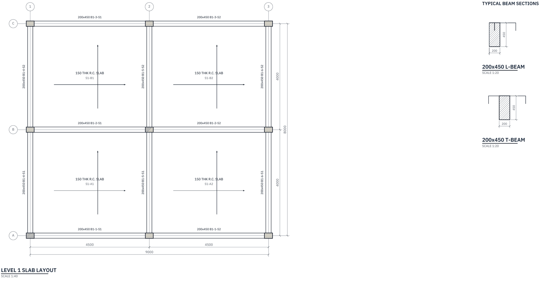
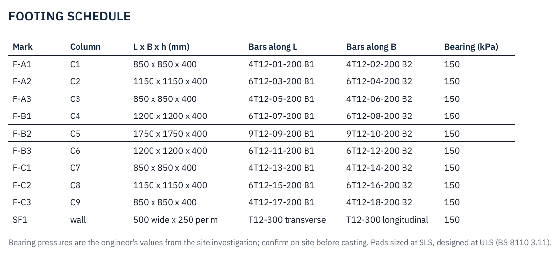
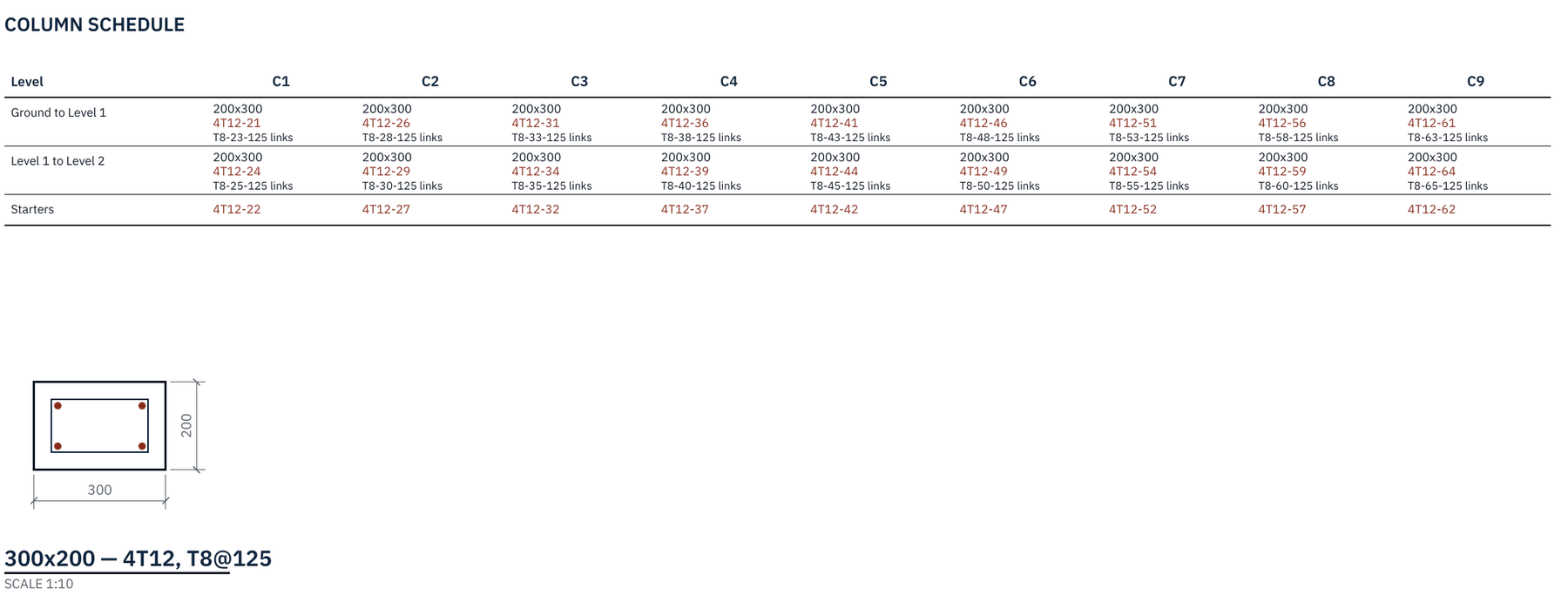
- Reinforced concrete frame, 2 × 2 bays of 4.5 × 4 m, 150 mm solid slabs on 200 × 450 beams and 300 × 200 columns, pad footings
- Scope
- Analysis, concrete design, detailing and the drawing set
Highlights
- Two suspended floors on solid slabs whose loads reach the beams by BS 8110 clause 3.5.3.7
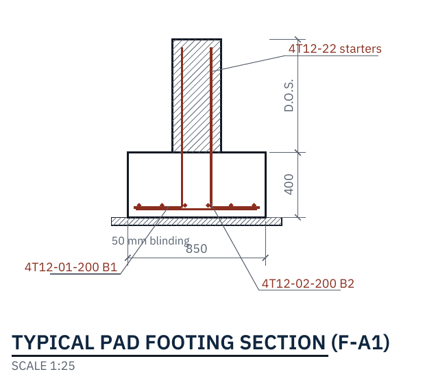
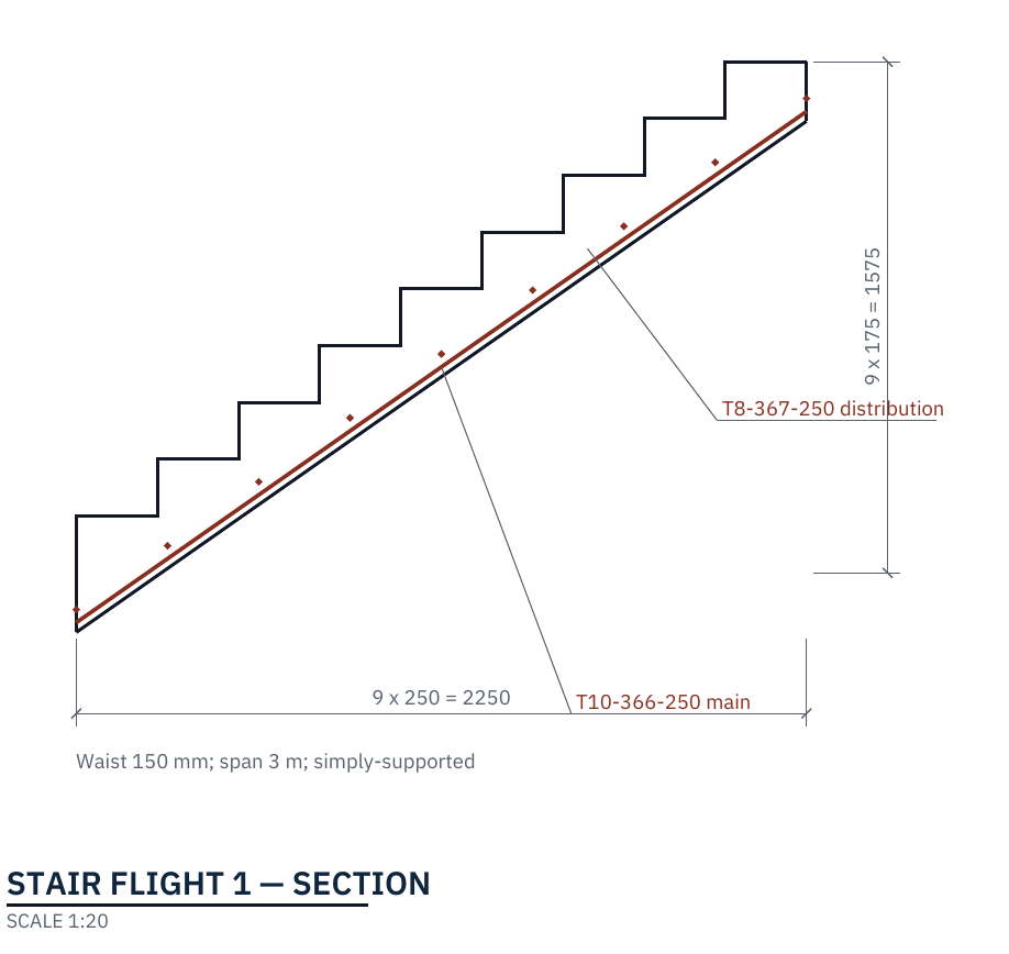
- Pad footings sized at 150 kN/m² allowable bearing, with the stair and the wall strip footing as separate calculators
- BS 8110-1:1997 Table 2.1 load combinations throughout
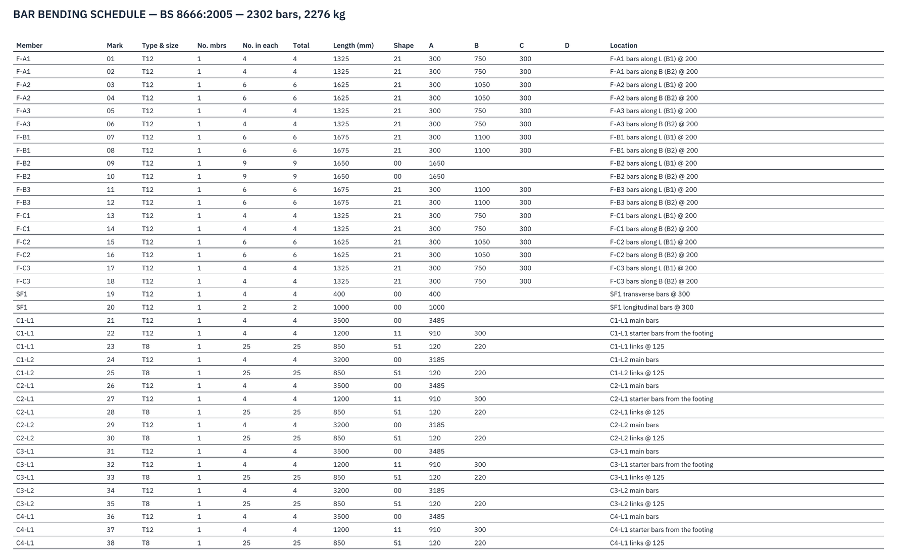
- Every member designed and detailed, with the bar bending schedule and drawing set generated from the same model
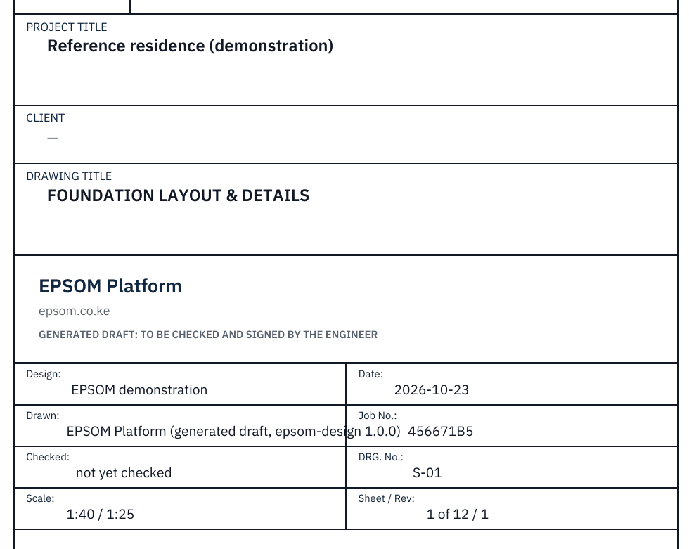
- Twelve drawing sheets, a 35-page design calculation report and a 31-page analysis report, each bound to the revision it came from
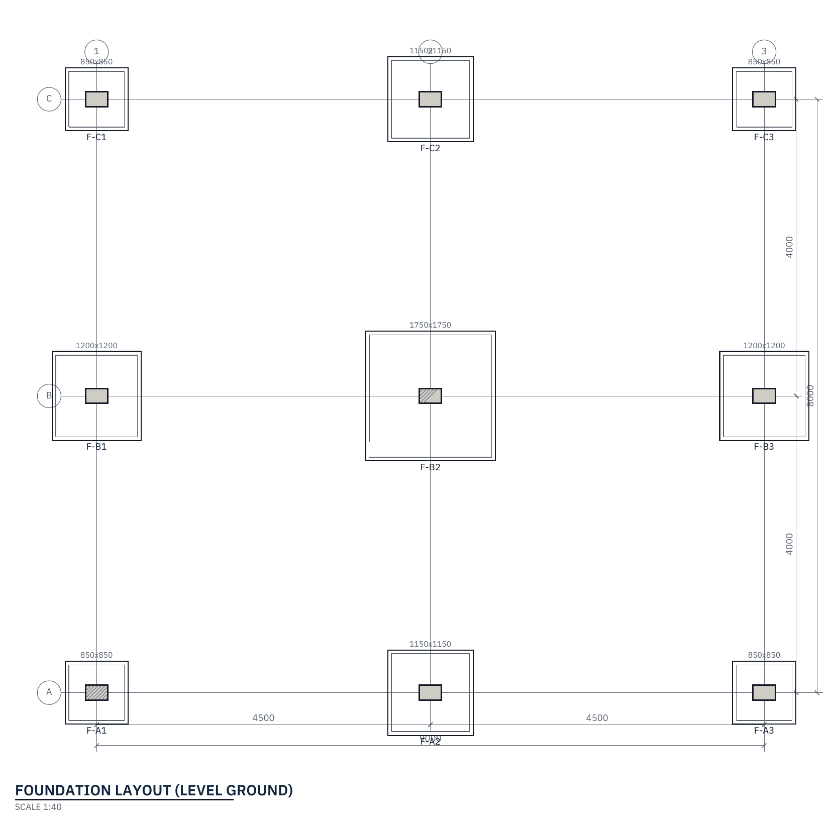
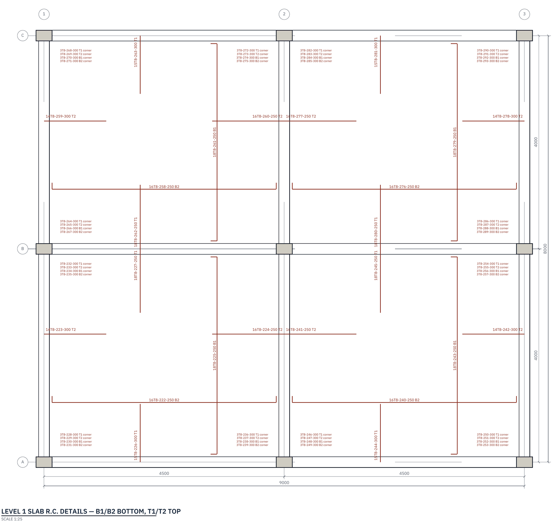

Drawings
What this demonstration shows
The platform's reference residence is a small building chosen because every part of a typical Kenyan house passes through it: a frame of beams and columns, suspended solid slabs, a stair, pad footings under the columns and a strip footing under the walls. The model is anonymised: its dimensions and loads are representative, and it is not any client's building.
From this one model the platform runs the frame analysis, designs every beam, column, slab, stair and footing to BS 8110-1:1997, details the reinforcement to BS 8666, and produces the calculation report, the design calculation report, the bar bending schedule and the drawing set.
What it is not
It is not a client project and it carries no engineer's approval. The drawings and reports on this page are the platform's own output, shown so that a client or a reviewer can see what the firm's engineers work from before they apply their own judgement and sign.